


Overall overview:
1. OG - 1000 Light Source: Capable of easily switching test spectra
2. High-precision reflective collimator
3. Lens bracket: Provides a firm and stable grip for the lens under test
4. Temperature drift module: used to test the performance of the lens at different temperatures
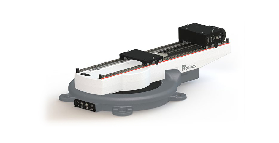
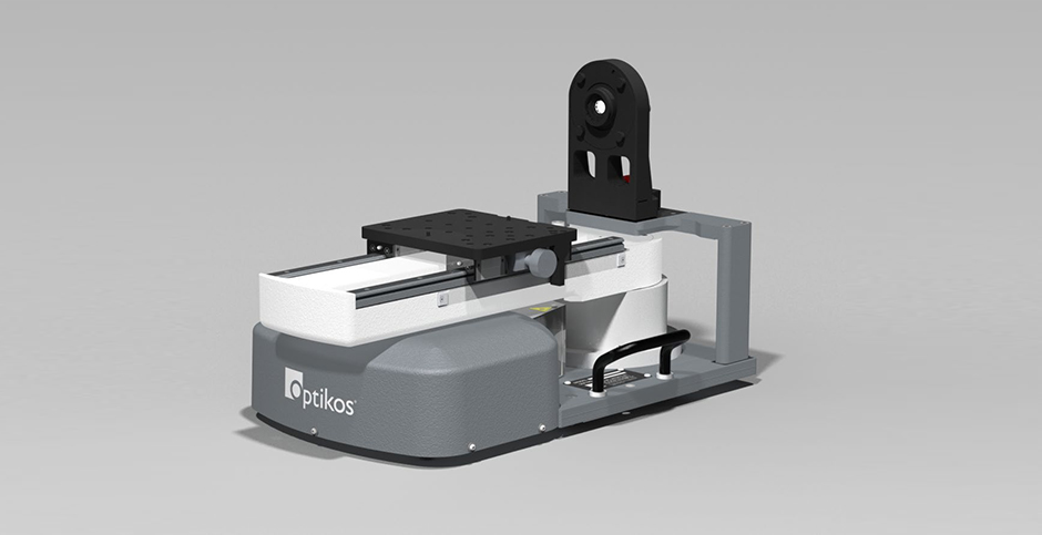
5. LP-1000 Lens Platform: A large-capacity platform for precise measurement of off-axis angular field points
6. Image analyzer: suitable for video and scanning applications
7. HC-1000 Handheld Controller: Bringing Hardware Control within Reach
8. AM-1000 Image Analyzer Stand: used for precisely positioning the lens under test
9. HC-1000 Handheld Controller: Bringing Hardware Control within Reach
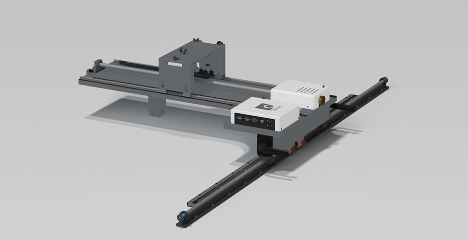
10. Finite conjugate platform: used for finite object distance testing
11. AF-1100 Achromatic Module: used for measuring achromatic lenses
-
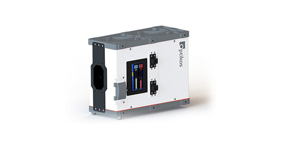
OG - 1000 Light Source
The OG-1000 series multispectral target generator utilizes the most advanced light sources, optical components, electronic control, and automation technology. These light sources provide uniform, high-intensity illumination ranging from ultraviolet to long-wave infrared (0.2 - 14μm). The device can be electronically switched between two coaxially aligned illumination channels (one equipped with a visible light source, and the other with an infrared or ultraviolet light source), enabling multispectral testing with just the press of a button.

·The color touch screen display provides an intuitive user interface for computer and module control
·The AlignMode function significantly enhances the speed of lens setup and alignment, while a single touchscreen button allows for switching from test configurations (visible light, infrared, or ultraviolet) to visible light alignment targets and back to the original configuration
·Optical path design aims to reduce loss and maximize output signal
·Single-shot setup for testing visible and infrared multispectral optical systems
1. OG-1000 series target generator model

2. OG-1000 Series Specifications


-
High-precision reflective collimator

A reflective collimator is used to project a light source to infinity to test an optical system with an infinite conjugate. The projection beam of the collimator should cover the entrance pupil of the optical system under test. This means that the clear aperture of the selected collimator should be larger than the entrance pupil of the system under test, and should include some additional aperture to accommodate the alignment tolerance of the test setup.
The standard reflective collimator provided by Optikos is an Off-Axis Paraboloidal Mirror (OAP), which ensures a surface accuracy of λ/8 (at 633nm) after installation and features an aluminum protective coating for multicolor testing. Each OAP is mounted in a high-stability bracket and includes a kinematic reference mirror for test bench alignment. The axis of most standard collimators is located 500mm above the optical platform.
Most OpTest test benches incorporate a folding mirror between the reflective collimator and the light source to minimize the overall footprint of the test bench. The size and position of the folding mirror used in a given system are determined by the collimator and other selected accessories.
3. Reflective collimator model

-
Lens mount
1. LM-300 Tilt/Pan Camera Mount
Each OpTest system includes the standard LM-300 tilt/pitch lens mount, which is a sturdy and stable fixture for mounting the lens under test. The LM-300 is bolted to the carrier of the LP-1000 rotating platform, which slides along high-precision steel linear guides and is equipped with a long-stroke linear encoder, allowing users to always know the position of the lens under test. Each standard OpTest test bench comes with a lens mount and a C-type mounting adapter plate. Additional adapter plates and mounting options are available upon request.
Schematic diagram of LM-300 tilt/pitch lens bracket

2. LM-300-XYZ Adjustable Tilt/Pan Lens Mount
When the OpTest test bench is configured for limited conjugate testing, an adjustable version of the LM-300 lens holder is provided. This version features a manual platform for positioning the lens under test along the X, Y, and Z axes (with a 100mm travel for each axis), allowing precise alignment with the light source at limited object distances.

3. LM-300 Standard Lens Mount Adapter
The lens mount adapter is compatible with various lens types, including threaded lenses and bayonet lenses. The lens adapter typically consists of a circular plate with appropriate lens mounting features at the center and a set of holes near the circumference, allowing the adapter plate to be mounted onto the LM-300 lens mount. Blank plates are also available for customers to add custom mounting features as needed.
Adapter plate for mounting LensCheck (LC) adapter plates onto LM-300 tilt lens bracket: The adapter plate shown below allows for the mounting of all LensCheck (LC) adapter plates onto the LM-300 tilt lens bracket.

4. OPT-LC-ADP adapter for using LensCheck adapter plate on OpTest LM-300 bracket

5. Breadboard for customized installation solutions
For customers who require more flexible installation options, Optikos offers a breadboard that can be directly mounted onto the LP-1000 carrier. Customers can build their own installation plan. The hole pattern on the breadboard can be 1/4"-20 threaded holes with a center-to-center distance of 1 inch or M6 holes, and two sets of mounting holes are provided so that the hole pattern can be centered or offset on the centerline of the LP-1000.

-
RM-1000 Rotating Lens Mount
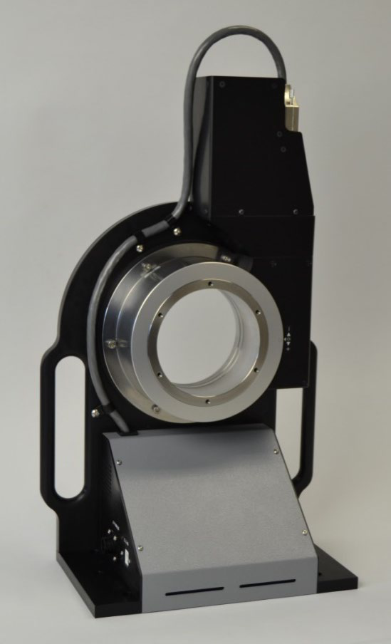
The OpTest test bench is designed to measure off-axis field points within a plane parallel to the surface of the optical table. These field points are obtained by rotating the lens under test around an axis perpendicular to the optical table. To acquire field points that are not within this plane, the lens must be rotated about its optical axis to bring the field points into the measurement plane. In a typical laboratory setup, this can be achieved by reinstalling the lens under test, but a more automated method is to use the RM-1000 rotating lens holder.
This component consists of an electric circular turntable mounted on a vertical plate. Users typically need to fabricate a suitable adapter plate to mount the lens under test onto the turntable. Both sides of the turntable can be used for mounting, and the specific choice usually depends on the size, back focal length, and mounting interface position of the lens under test.
RM-1000 System Specifications:
Total movement range: ±360°
Resolution: 0.002°
Repeatability: 0.005°
Inner diameter: 110mm
Load capacity (newtons): 36,000/(93 + D), where D (unit: mm) represents the distance from the center of the rotating ring mounting surface to the center of mass of the unit under test
-
A novel temperature drift module for testing the performance of lenses at different temperatures
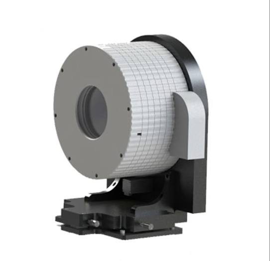
The temperature test module enables users to measure the same performance parameters as the standard OpTest test bench, but with the lens under test placed in a temperature-controlled and insulated chamber. These modules can be directly mounted on the LP-1000 stage, replacing the standard lens holder, facilitating integration with the rest of the OpTest system. The temperature of the module is controlled by an external circulation device (not shown in the figure).
These modules are particularly suitable for measuring the image plane position changes of the tested lens within its operating temperature range, and can also be used to verify the performance of athermal lens components. The temperature test module is equipped with a customized Invar mounting interface to facilitate the positioning of the mounting flange of the tested lens outside the chamber. This allows for measuring the flange focal length at different temperature points without opening the chamber and directly contacting the lens mounting flange.
For more information, please refer to the temperature drift module data manual or contact us.
-
Image Analyzer
The image analyzer captures the image formed by the tested optical system and converts the optical image into an electronic image with sufficient spatial resolution for analysis by OpTest 7 software. Optikos employs two image acquisition methods: video and scanning. The most suitable system type for a specific application depends on the type of tested optical system and the testing environment.
A video image analyzer captures images by magnifying (at a certain magnification) the image onto an image sensor, such as a CCD or a microbolometer array.
The scanning system acquires image information by measuring the changes in light intensity as edges or slits move across the image plane.

-
LP-1000 Lens Platform

When illuminating off-axis infinite conjugate field points, it is not practical to rotate the long focal length collimator and light source. Therefore, OpTest adopts the method of using a fixed collimator and rotating the lens. The platform for mounting the lens is the LP-1000, and since the image analyzer must remain fixed relative to the lens under test, it is also mounted on the LP-1000. Optikos engineers designed the structural castings in the LP-1000 using finite element analysis to ensure that they maintain flatness when mounted on the optical table. This improves upon the traditional guide rail system that is directly mounted on the optical table, which is prone to bending due to insufficient surface accuracy of the optical table.
The unique cable management system prevents cables from dragging on the optical tabletop, thereby avoiding the introduction of errors into centroid measurement procedures such as effective focal length, distortion, principal ray angle, lateral chromatic aberration, and so on.
The main load-bearing surface has been protected to minimize contamination and achieve high integration.
The lockable lens platform and image analyzer carrier move on a stainless steel linear guide rail aligned with a granite reference, ensuring straightness.
Integrated linear encoder for long flange and back focus measurements.
LP-1000 system specifications:
Total rotational range: ±150°
Rotary encoder resolution:<0.1 arc seconds
Free linear travel (optical track): The distance between the lens holder carrier and the image analyzer carrier is 750mm
Linear encoder resolution: 0.002mm
Software / Control: Remote Control (OpTest): Remote control is achieved through the HC-1000 handheld controller; it can also be controlled using the native OpTest 7 software; a comprehensive command set is provided, allowing users to develop custom software or test macros.
mechanical
Floor area: Diameter 80cm
Weight: 77kg
Maximum load capacity: 80kg
-
VideoMTF® Image Analyzer
For systems based on focal plane arrays or image sensors, the VideoMTF image analysis module enables rapid image scanning and direct image viewing. This speeds up and simplifies system setup, as the image position and optimal focal plane can be quickly determined.
1. VI-1000 Visible Light Image Analyzer (400 - 1000nm)
- Spectral response range: 400 - 1000nm
- The integrated flipping mirror component allows for switching between electronic imaging and direct manual observation of image spots
- Achromatic tube lens; high-sensitivity camera, 12-bit video output
- Use a flat-field apochromatic, high numerical aperture Nikon objective lens as a relay lens (sold separately)
2. VI-2000 Short-Wave Infrared Image Analyzer (900 - 1700nm)
- Spectral response range: 900 - 1700nm
- Integrated flip mirror assembly allows for image observation using visible light
- Custom-designed tube lens; high-sensitivity camera with Camera Link digital video output
- Use Mitutoyo near-infrared objective lens as a relay lens (sold separately)
3.VI-4000 Long-wave Infrared Image Analyzer (7.5 - 14μm)
- Uncooled microbolometer
- Spectral response range: 7.5 - 14μm
- resolution 320×240
- Calibrated long-wave infrared objective lens: magnification 7.5 times; numerical aperture 0.70

VI-1010 Visible Image Analyzer
(shown without relay lens)

VI-4000 LWIR Video Image Analyzer and Relay Lens
-
EROS™ Image Analyzer
The knife-edge scanning system offers greater flexibility in testing a wider range of optical systems. Compared to array detectors, there are more types of single-element detectors. The acquisition and relay optical elements do not need to achieve the image quality required for video analysis. When using an EROS image analyzer, the relay optical elements collect light from the image plane of the optical element under test and project it onto the detector. The sampling resolution is determined by the mechanical step size of the platform that carries the image analyzer.

1. SD-500 Short-Wave Infrared / Mid-Wave Infrared Scanning Image Analyzer (1 - 5.5μm)
·It consists of a short-wave infrared/mid-wave infrared detector, relay optics, a scanning aperture assembly, and an ultra-compact electric rotating component (used to switch the direction of the analysis aperture between tangential and sagittal scanning).
·The unique geometric structure of the SD-500 enables it to use probes with a diameter of < 19mm to measure at distances up to 56mm from the recessed image plane.
·The detector assembly is an indium antimonide detector cooled by liquid nitrogen (covering the 1 - 5.5μm range), which integrates a matched preamplifier and temperature sensor within an 8-hour insulated Dewar vessel.
·The multi-element relay lens collects light from a scanning diaphragm with a maximum f-number of 0.7. The scanning diaphragm set includes a slit with a nominal width of 2.5μm and a knife edge, both of which are metal films on a sapphire substrate.
2. SD-600 Long-Wave Infrared Scanning Image Analyzer (7 - 13μm)
·It consists of a long-wave infrared detector, relay optical elements, a scanning diaphragm assembly, and an ultra-compact electric rotating component (used to switch the direction of the analysis diaphragm between tangential and sagittal scanning).
·The unique geometric structure of the SD-600 enables it to use probes with a diameter of < 19mm to perform measurements at distances up to 56mm from the recessed image plane.
·The detector assembly is a liquid nitrogen cooled HgCdTe detector (7 - 13μm sensitivity) that integrates a matched preamplifier and temperature sensor within an 8-hour thermal insulation Dewar vessel.
·The multi-element relay lens collects light from a scanning diaphragm with a maximum f-number of 0.7. The scanning diaphragm set includes a slit and a knife edge, both of which are metal films on a zinc sulfide substrate.
3. SD-100-UV UV Scanning Image Analyzer (220 - 500nm)
·It consists of an ultraviolet detector, relay optical elements, a scanning diaphragm, and a preamplifier. The novel scanning diaphragm design allows for simultaneous tangential and sagittal scanning.
·The detector component is a super-sensitive photomultiplier tube with a response range of 220 - 500nm. The multi-element relay lens collects light from a scanning diaphragm with an f-number of 0.7. The scanning diaphragm is a metal film on a UV-grade fused silica substrate.
-
The new EROS™ image analyzer for testing folding optical systems
These two newly designed components provide greater flexibility when measuring folded lens components with recesses or obstructions in the image plane position.

1. SD-800 Shortwave Infrared/Mid-Wave Infrared Scanning Image Analyzer (1 - 5.5μm) for Folding Unit Under Test (UUT)
·It consists of a short-wave infrared/mid-wave infrared detector, relay optical elements, a built-in turning mirror, a scanning diaphragm assembly, and an ultra-compact electric rotating component.
·The SD-800's internally precision-aligned turning mirror can be used to access hard-to-reach image planes in complex folded optical components, reaching image planes with a recess depth of up to 25mm and bypassing components as large as 120mm.
·The flexible design allows the detector head to rotate to four different folding test directions: up, down, left, and right, making it suitable for measurements of various optical and mechanical designs.
·The customized motor design allows for the rotation of the scanning diaphragm, enabling automatic measurement in both tangential and sagittal directions.
·The fully configurable software package allows for the realignment of the coordinate system and platform axes to accommodate the folding test configuration of the SD-800.
·The detector assembly is an indium antimonide detector cooled by liquid nitrogen (with a sensitivity range of 1 - 5.5μm), which integrates a matched preamplifier and temperature sensor within an 8-hour thermal insulation Dewar vessel.
·The multi-element relay optical element collects light from scanning apertures with an f-number up to 0.7. The scanning aperture set includes a slit and a knife edge, both of which are metal films on a sapphire substrate. All the functions of the non-folded SD-500 are retained.
2. SD-900 is a long-wave infrared scanning image analyzer (7 - 13μm) used for folding UUT
·It consists of a long-wave infrared detector, relay optical elements, an internal turning mirror, a scanning diaphragm assembly, and an ultra-compact electric rotating component.
·The SD-900's internally precision-aligned turning mirror can be used to access hard-to-reach image planes within complex folded optical assemblies, reaching image planes with recesses up to 25mm deep and bypassing components as large as 120mm.
·The flexible design allows the detector head to rotate to four different folding test directions: up, down, left, and right, making it suitable for measurements of various optical and mechanical designs.
·The customized motor design features a rotatable scanning diaphragm, enabling automatic measurements in both tangential and sagittal directions, as well as astigmatism measurements.
·A fully configurable software package that allows for the realignment of coordinate systems and platform axes to accommodate the folding test configuration of the SD-900.
·The detector assembly is a liquid nitrogen-cooled HgCdTe detector (with sensitivity ranging from 7 to 13μm), which integrates a matched preamplifier and temperature sensor within an 8-hour insulated Dewar vessel.
·The multi-element relay optical element collects light from a scanning diaphragm with a maximum f-number of 0.7. The scanning diaphragm set includes a slit and a knife edge, both of which are metal films on a zinc sulfide substrate. All the functions of the non-folded SD-600 are retained.
-
AM-1000 Image Analyzer Holder: Used for precisely positioning the lens under test
The AM-1000 places the image analyzer on the image plane of the lens under test and defines the following three-axis coordinate system in the image space of the lens under test:

·X-axis: Adjust the horizontal image height parallel to the optical table surface.
·Y-axis: Adjust the image height perpendicular to the optical tabletop.
·Z-axis: Perform focus adjustment along the optical axis.
AM-1000 adopts Optikos' patented motion control system, integrating intelligent motion control circuits and modules, with all calibration parameters stored locally.
System Specifications:

-
HC-1000 Handheld Controller
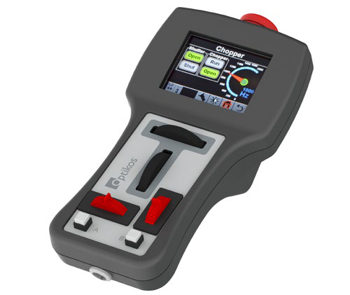
Test benches equipped with the Optikos Motion Control (OMC) system typically feature a computer running OpTest7 and a HC-1000 handheld controller. The HC-1000 provides remote access to various functions primarily accessed through the main OpTest 7 window, enabling users to operate the test bench even when away from the computer.
Remotely control and display the positions of all OMC axes.
·Remote control OG-1000 series target generator.
·Lock the display of the amplifier signal level.
·The function of a flashlight for working in a dark room.
·Emergency stop buttons for all axes.
·The direction controlled by any pair of touch points can be reversed.
·Two easily programmable waypoints allow for the return of all axes to their defined positions with a single button press.
Mechanical specifications:

-
Finite conjugate platform

Not all lenses can be tested under infinite conjugate conditions. In these cases, the FP-1100 finite conjugate platform is required. This component includes a kinematic interface for the target generator and a long-stroke linear bearing orthogonal system, which can be used together to set the object height and distance for testing. The horizontal axis on the FP-1100 is motorized and equipped with a linear encoder, while the object distance is manually set and locked. A threaded fine adjustment device is provided, and a second linear encoder runs through the entire stroke.
The FP-1100 can be used standalone or shared with a collimator device on the optical tabletop. Due to its kinematic mounting structure, the same OG-1000 series target generator can be shared between the collimator and FP-1100. Even when conducting limited conjugate testing, the LP-1000 lens platform (see below) is still used to support the lens holder and image analyzer. In this case, the object distance can be determined by the sum of readings from the FP-1100 linear encoder and the encoder on the LP-1000 rotator.
·The integrated Optikos motion control system reduces wiring and allows for control of object height through the Optest7 and HC-1000 handheld controllers.
·There is an adjustable stop block on the z-axis guide rail.
·The drag chain on the horizontal axis neatly manages all the cables of the target generator.
·The low stage height ensures that when two components share the same test bench, there is no obstruction of the light beam to any standard Optikos collimator.
System Specifications:

-
AF-1100 Afocal Module

AF-1100 is a component of LP-1000, and it is crucial when the lens under test cannot form a real image. In such cases, an auxiliary "divergent lens" needs to be introduced on the collimated output path to form a real image for analysis. To minimize the impact of the divergent lens on the measured modulation transfer function (MTF), it must be ensured that it is always used only on the optical axis.
That is to say, the optical axis of the diverging lens and the image analyzer must follow the principal ray of the tested afocal lens. In addition to the rotation required for setting the field angle for measurement, a second rotation is also necessary, and this second rotation is achieved by the AF-1100 afocal module mounted on the LP-1000 lens carrier. The OpTest7 software provides installation suggestions for the lens and AF-1100 based on the parameters of the tested lens. Among them, the spacing between the two rotation axes and the placement of the diverging lens at the exit pupil position of the tested lens are particularly important. The correct settings can minimize the offset of the entrance pupil of the tested lens in the collimated beam.
·Suitable for both erect and inverted afocal lenses.
·It provides a clear platform interface for users to design their own lens mounts.
·A clear connection bridge interface is provided for placing the external pupil and the diverging lens.
·Equipped with an adjustable aperture and a 50mm diverging lens, it is suitable for measurements with various visual instruments.
·The calibration mode in OpTest7 aids in determining the position of the external exit pupil plane during lens installation.
System Specifications:

-
OpTest® 7 Software
The core of OpTest 7 is a software application that integrates with all OpTest and LensCheck systems. It is used to control electronic hardware components and electric moving parts, collect and analyze video and scanning detector signals, and graphically display measurement results to users.
OpTest 7 runs on Windows 7 systems and includes a licensed version of Microsoft Excel with every installation. All measurement data can be directly exported to formatted Excel workbooks, making it easy to incorporate into customer reports and other documents.
Precision measurement for a wide range of users: OpTest 7 not only enables various users to utilize precision measurement technology, but also ensures the application's continued use across future generations of operating systems through careful consideration of the underlying architecture. It utilizes the latest Microsoft programming environment and separates the graphical user interface from the application code.
OpTest® 7, v1.8 introduces Python™ scripting functionality and supports new OpTest modules: OpTest 7's flexible platform supports multiple measurements; now, Python™ scripting functionality has been added through an integrated editor, while maintaining support for OLE (Object Linking and Embedding) through COM objects in traditional programming environments such as Microsoft Excel VBA. OpTest 7 also supports new OpTest finite conjugate and afocal modules.
Easily select the interface that meets your information needs: OpTest software was originally designed for engineers, providing operators with a single interface that enables anyone using the software to access all complex control and processing functions. OpTest 7 features multiple operation modes designed to meet the needs and technical levels of different users. This makes OpTest 7 a powerful laboratory tool in engineering mode, while ensuring ease of use for production operators in production mode. Early versions of OpTest required the use of separate macros to measure parameters such as focal length and field curvature, whereas OpTest 7 can set and execute measurements in an easy-to-understand manner, including many first-order parameters such as focal length and field curvature. It allows users to easily perform a series of measurements without writing macros and extract many measurement results from a single data structure. OpTest 7 can also automatically and intelligently select parameters such as camera gain, exposure, and sample reticle width, eliminating the need for operators to make manual selections.